Advanced Servo Tester
Overview
RC Servo testers today fall into two categories:
- Cheap servo testers
- One button to cycle through 3 modes
- Often inaccurate centering.
- Expensive servo testers that offer a lot more functionality
- Cost $60+
- Take significant time to start up.
- Take multiple key presses to get to basic functions.
The specific frustration that initiated this project was cycling through modes to get between Manual and Center. I have broken control horns and stripped gears by cycling through Sweep to reach Manual mode.
So I built a servo tester that offers more functionality than the low-cost ones, but at a more affordable price than the expensive ones.
Features
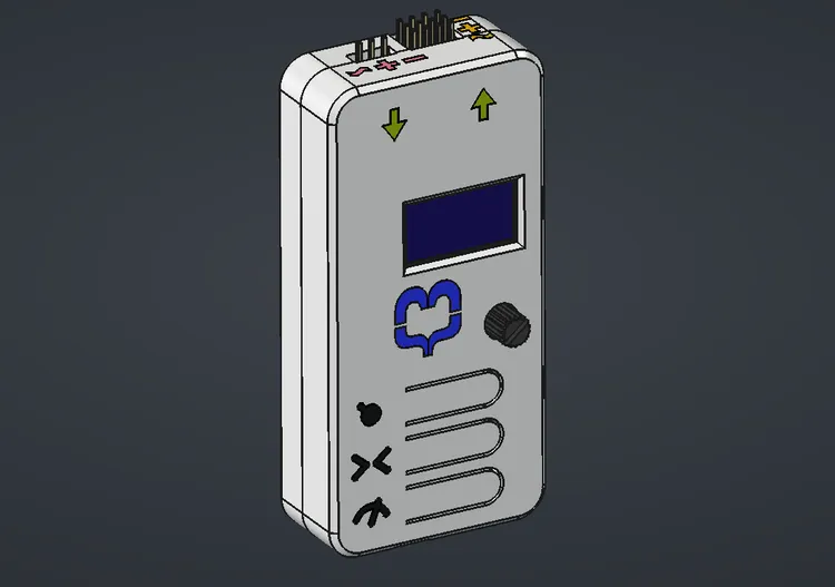
Three buttons
Three modes, each with their own dedicated button:
- Manual Mode
- Center Mode
- Sweep Mode
Sweep Speed Control
When in sweep mode, the sweep speed can be adjusted from 0.1 seconds to 2.0 seconds.
Manual Mode
Adjustable PWM from 1000 to 2000 microseconds using a potentiometer.
Center Mode
Center mode is stable and accurate, regardless of input voltage. This is important. A number of my low-cost servo testers have centers that change depending on the input voltage.
Additional Features
There are additional features not covered here — those features I am keeping secret for now.
Design Process
Doing this project sent me down a few different rabbit holes:
- Embedded programming using Arduino
- Circuit design using KiCad
- Attempting to use AI to help with the design process.
- Using Sketches, Assemblies, and Components in FreeCAD to accurately align objects on the 3D-printed case.
Arduino programming
I have done some Arduino programming before, but this was a deeper dive than previous projects. In previous projects I have used the Arduino IDE, which is functional but limited — it offers minimal syntax highlighting and no code completion.
So I switched to CLion from JetBrains. With the PlatformIO plugin, I have an IDE I am familiar with. It offers code completion, syntax highlighting, dependency management, and code analysis.
Fairly far along in the project, I ran into a performance problem. Instead of getting a stable 50 Hz I was getting jumpy, unstable PWM. It turns out the problem was that I was using an SSD1306 OLED with I2C communication, and the Adafruit display library. Using the Adafruit library meant that the whole display was being updated every time the screen changed. This was taking up all the memory, and updating the display was taking 40+ ms, which meant the Arduino could not keep up with the 50 Hz PWM rate. I replaced the Adafruit library with the SSD1306AsciiWire library and rewrote the display code to only update the parts of the screen that changed. This reduced the average screen refresh time down to less than 10 ms, allowing the Arduino to keep up with the 50 Hz PWM rate.
Dropping the Adafruit library also reduced RAM usage because it maintained a full-screen buffer that consumed a large portion of the Arduino’s limited memory.
Lessons learned here:
- Arduino microcontrollers have very limited RAM.
- Adafruit libraries trade RAM for functionality.
- I2C is slow, even at 400 kHz.
Circuit design
The last time I designed a circuit was in the early 2000s. It was part of an entry level electronics class, and the circuit was fairly basic.
AI tools have improved significantly, and I hoped they could help with the design process. I told Claude about the project, and it helped me design what looked like a solid circuit. I wanted the board to accept power from the power input port, the servo output port, or the Arduino’s USB port.
I wanted to be precise about power loss and prevent reverse polarity, so I was trying to build and use an “ideal diode” to direct the power through the various power rails. I also designed it using “high side switching,” meaning the FETs were on the positive side of the circuit.
I used wokwi to do a very early virtual prototype of the circuit. Wokwi does not have FETs, but it does have relays which can be used to simulate P-channel and N-channel MOSFETs. So that is what I did. I emulated N-channel MOSFETs using relays on the high side of the circuit. It worked exactly as I wanted it to.
From there, I moved to KiCad, designed the circuit, and selected components.
Once I had the design in KiCad, I built a physical prototype on a breadboard. The prototype worked as I wanted it to. However, I was losing more voltage than I expected. I attributed this to using through-hole components rather than the surface-mount ones the final PCB would use.
Comfortable that the circuit worked, I exported the Gerber files and sent it off to JLCPCB to have some boards made.
As soon as the boards arrived, I realized I had made a mistake. I had used the Adafruit SSD1306 footprint but had not bought the Adafruit module. I bought some simple 128x64 I2C SSD1306 modules. These modules are compatible with the Adafruit SSD1306 I2C but have a very different footprint.
Luckily, the four pins that matter to the circuit match, but the screen ends up off-center and lower than planned.
After assembling the first board, I was still losing more voltage than expected. Only then — too late — did I realize that AI had led me down a dead end. N-channel MOSFETs require the gate voltage to be higher than the source voltage. I was using the 5 V from the Arduino as the gate voltage and trying to switch a 6 V source.
I had three options:
- Add in a voltage booster (charge pump) to boost the gate voltage above that of the supply voltage.
- Redesign the whole thing using low side switching and P-channel MOSFETs.
- Give up on the idea of “Ideal Diode” and use simple Schottky diodes instead.
Since the circuit already had Schottky diodes in it, and the voltage loss was acceptable, I went with option 3. This also meant that not only could I use the components I already had, I could still use the PCBs that I had created by simply flipping one diode around, shorting out another, and bridging a third diode instead of a MOSFET.
Lessons learned here:
- Do not trust AI to be correct about hardware specifics.
- Do not overcomplicate. Perfection is the enemy of done.
- Quadruple-check your footprints before ordering the boards.
Case design
I use FreeCAD for all of my 3D CAD work, but the case for this project had a couple of extra challenges. First, I wanted to design the case accurately around the PCB and components. Second, I wanted it to be multicolor.
KiCad and FreeCAD work well together. In KiCad, I imported the correct SSD1306 module, aligned it to the Adafruit footprint, loaded in the rest of the components, and then exported the whole PCB with all components as a 3MF (3D Manufacturing Format) file.
In FreeCAD, I imported the 3MF file and started work on the case. Using the actual PCB dimensions as a guide, I was able to create an accurate case quickly.
The more challenging part was getting the case to be multicolor. I tried the lazy route first and sketched all the icons directly onto the case, but this made it difficult to create the secondary bodies used for multicolor 3D printing.
I ended up reverting to the blank case and taking a detour to figure out how to:
- Create separate bodies for each icon/label
- Create components to hold the separate bodies as a grouped object.
- Use a sketch inside an assembly to accurately position the components.
- Import those back into the main case design as cutting tools and as printable bodies.
Final Result
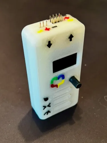
The result is a functional servo tester that met all of my original requirements — and exceeded a few.
I ended up building a few of these, so I am planning to sell some on eBay. They are not production quality, but they are fully functional, more capable than the low-cost options, and can be priced below the overcomplicated expensive testers.